Printing

Pillars can indent into ejector back plate

Around 1450 Gutenberg used a press to accomplish 2D printing. Within this press were shaped inserts retained by a holder. From these humble beginnings we now do 3D printing in 10,000 ton presses. It is called high pressure die casting. Many of the challenges are the same. The inserts and the holder must be strong enough to withstand the applied pressure of the press.

Designing the ejector side of the die has always been challenging. A hollow for the ejector plate must exist behind the insert(s). This is exactly where support is needed. The normal practice is to utilize support pillars. The desired shape of the final casting imposes restrictions on where ejector pins can be located. Many times the placement of ejector pins results in smaller pillar diameters that we would like. Pillars that are too small in diameter print into the ejector back plate (or platen) and the holder. This results in a casting with incorrect dimensions. A printed back plate is pictured. Using a pllar that has a mushroom back end and a front end contacting the back side of the insert itself is the easiest fix. 45 Rc material can be used to make this pillar such that it does not print under load.

Quick Replace

extract style core pins simplify core swap after booking die

Book em Dan O

I was thinking back to favorite TV shows when writing this post. The villains were chastised with the famous book em Dan O I say the same thing when a core pin breaks. “Book EM” Most of the dies that I cast provide for quick replace of cores and ejector pins. Access to a broken core or pin is accomplished by booking the die in the machine. The booking straps and the clamp motion expose the back of either the cover or ejector die. Set screws or clamp plates open an access passage to the pin. Better fragile core designs include either a core with a threaded extract hole or a clamp element which can be used to pull the core from the back side. Even more useful in saving effort is front load cores however this does not apply to bent ejector pin replacement which involves booking a die at a minimum.

STEEL SAFE

Machining fixtures use datums to locate castings

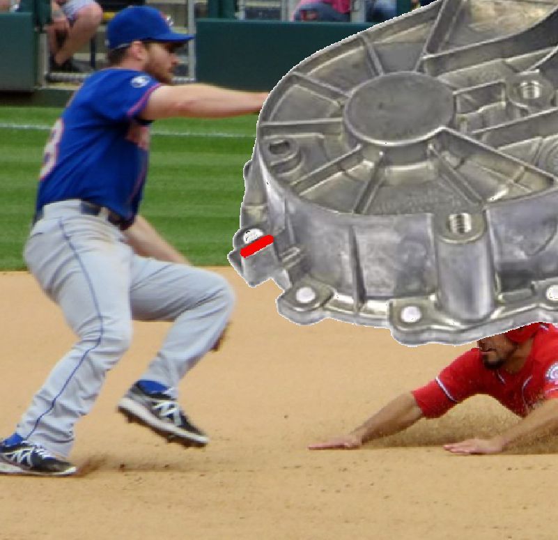
We are all aware that welded surfaces on high pressure casting die inserts prematurely heat check. Heat check is not something that we want on machining datum surfaces. In the pictured transfer case casting the part rests on three ears in the machining fixture. I have colored the datum surface on one ear red. The dimensional accuracy of this surface will determine whether sufficient machining stock is provided on the rest of the casting.

One of the most effective methods of reducing exposed porosity is to reduce machining stock thickness. This is because the skin of a high pressure aluminum die casting is porosity free due to rapid solidification. As we reduce the provided stock thickness shrinkage and warp of the casting becomes a factor in reliably achieving machining clean up

Skilled die cast shops have discovered that a more accurate casting shape can be achieved if the die shape is biased to correct for warp. This is accomplished by adjusting the die shape using a first sample casting. Certain area on the mold are initially created with ..25 mm extra mold steel. This is where we get the term “steel safe” The pictured datum surface is a prime example. It is unacceptable to bias a mold shape to compensate for warp by welding datum surfaces. Adding extra steel makes weld free correction possible.