Rigid

Large High Pressure Die Cast Flash

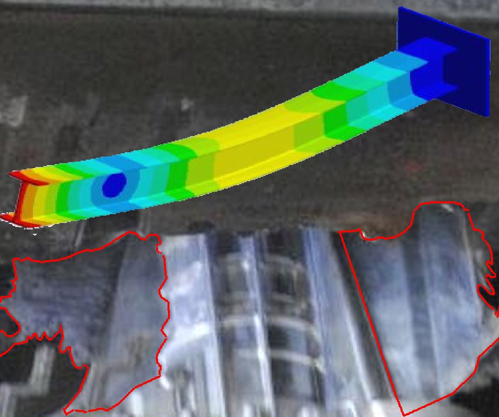
One of the early lessons taught to mechanical engineers is that materials deflect under applied loads. I can assure you that there is no shortage of applied loads in high pressure die casting. I thought that a 1000 ton press was massive as a new die cast engineer. Now we see 10,000 ton high pressure die casting presses. When you see the blocks of steel used to make high pressure die cast platens, it is hard to picture them flexing

This discussion is about the flexing of the ejector platen. On a 400ton die casting machine you can pretty much ignore ejector platen flexing. The ejector die itself is rigid enough to bridge across the platen face. On a 4000 ton die cast machine platen flex is an important consideration. The style of clamping mechanism is also a factor. There are four common styles.

Vertical pin axis book links

Horizontal pin axis book links

4 corner links

Hydraulic cylinder 2 platen

It is usually necessary to design the ejector die to match the style of machine clamp. Dies run in machines that they were not designed for are well known for flashing.

Large dies with slides will flash. Even if you are able to blue the die to shut off at steady state temperature, the first shot is not at steady state. Die require 30 to 100 shots to reach steady state even with preheat. Properly designed dies eject all flash every shot. This avoids die damage related to closing on flash. Remember the machine could be applying 10,000 tons on a small piece of flash

Printing

Pillars can indent into ejector back plate

Around 1450 Gutenberg used a press to accomplish 2D printing. Within this press were shaped inserts retained by a holder. From these humble beginnings we now do 3D printing in 10,000 ton presses. It is called high pressure die casting. Many of the challenges are the same. The inserts and the holder must be strong enough to withstand the applied pressure of the press.

Designing the ejector side of the die has always been challenging. A hollow for the ejector plate must exist behind the insert(s). This is exactly where support is needed. The normal practice is to utilize support pillars. The desired shape of the final casting imposes restrictions on where ejector pins can be located. Many times the placement of ejector pins results in smaller pillar diameters that we would like. Pillars that are too small in diameter print into the ejector back plate (or platen) and the holder. This results in a casting with incorrect dimensions. A printed back plate is pictured. Using a pllar that has a mushroom back end and a front end contacting the back side of the insert itself is the easiest fix. 45 Rc material can be used to make this pillar such that it does not print under load.

Quick Replace

extract style core pins simplify core swap after booking die

Book em Dan O

I was thinking back to favorite TV shows when writing this post. The villains were chastised with the famous book em Dan O I say the same thing when a core pin breaks. “Book EM” Most of the dies that I cast provide for quick replace of cores and ejector pins. Access to a broken core or pin is accomplished by booking the die in the machine. The booking straps and the clamp motion expose the back of either the cover or ejector die. Set screws or clamp plates open an access passage to the pin. Better fragile core designs include either a core with a threaded extract hole or a clamp element which can be used to pull the core from the back side. Even more useful in saving effort is front load cores however this does not apply to bent ejector pin replacement which involves booking a die at a minimum.

STEEL SAFE

Machining fixtures use datums to locate castings

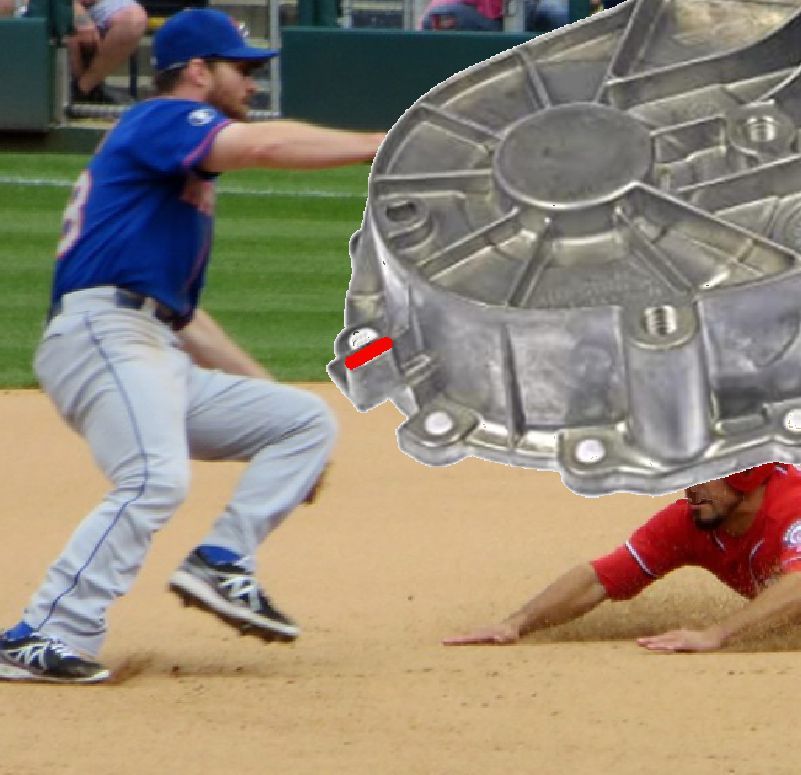
We are all aware that welded surfaces on high pressure casting die inserts prematurely heat check. Heat check is not something that we want on machining datum surfaces. In the pictured transfer case casting the part rests on three ears in the machining fixture. I have colored the datum surface on one ear red. The dimensional accuracy of this surface will determine whether sufficient machining stock is provided on the rest of the casting.

One of the most effective methods of reducing exposed porosity is to reduce machining stock thickness. This is because the skin of a high pressure aluminum die casting is porosity free due to rapid solidification. As we reduce the provided stock thickness shrinkage and warp of the casting becomes a factor in reliably achieving machining clean up

Skilled die cast shops have discovered that a more accurate casting shape can be achieved if the die shape is biased to correct for warp. This is accomplished by adjusting the die shape using a first sample casting. Certain area on the mold are initially created with ..25 mm extra mold steel. This is where we get the term “steel safe” The pictured datum surface is a prime example. It is unacceptable to bias a mold shape to compensate for warp by welding datum surfaces. Adding extra steel makes weld free correction possible.

Chip Free

Shigeo Shingo was a leading expert in the Toyoda production system as a Japanese industrial engineer. Many current industrial best practices can be traced back to his teaching. This post is on on only one of his teachings. Manufacturing is more cost effective if you utilize processes that do not make chips. This sounds like an impossible command if you are a manufacturer who specializes in machining.

No Shingo was not trying to put all machining suppliers out of business. Some of the processes that machining houses perform can be accomplished chip free. Many chip free processes are the result of a tighter working relationship between the die caster and the machining house

  1. Cast chamfers or cast chamfers with counter bores can replace machined chamfers.
  2. Form taps can replace cut taps a) Form taps have 5 times the life b) Form taps tolerate some porosity in the bosses c) Structural alloys such as 356 need the work hardening of a form taps to achieve sufficiently strong threads
  3. Orbitformed cast studs can replace screwed connections
  4. Roll burnishing can solve microporosity in bores
  5. Welding is chip free

As die castings get larger we get more concerned about the foot print of the total operation. One of the nice things about chip free operations is that they can be accomplished in final assembly. Moving a part from station to station does not add value. It becomes possible to do less moves if the number of stations is reduced. This means that each station has more operations. Many of my more recent manufacturing cells implement chip tree operations such as form tapping in stations downstream of the CNC machining centers. I have discovered that a tapping head is less expensive per spindle when compared to a CNC machining center spindle

Solder

Hardness Testing Files

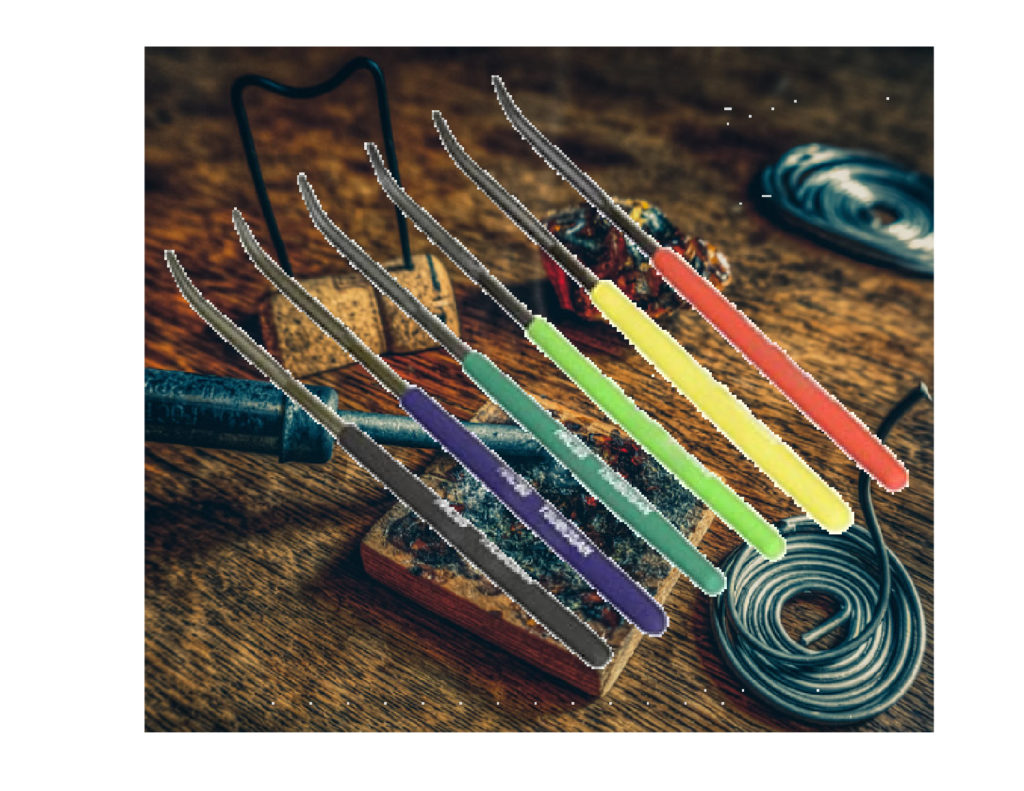
There is no need to 100% inspect the surface hardness of the aluminum casting die inserts. The molten metal will do that for you. Molten metal will highlight the areas that are softer than the expected Rc 44 to Rc 50 range. Aluminum will solder to soft insert surfaces. Due to the physics of heat treatment the insert material at the bottom of the ribs is most likely to be out of specification. Unfortunately cleaning solder out of ribs is very difficult and is almost 100% likely to cause castings to stick in the die. Die casters such as Briggs and Stratton invented laminated dies for their deep fin lawn mower heads to enable creation of proper die insert hardness and draw polish access at the bottom of the fins.

As the die caster, you normally rely on the die shop to confirm the quality of the heat treat. Usually it is too late to fix improper heat treat after the insert is cut to final size. A set of hardness testing files and a visit to the die shop when the inserts are returned from heat treat are even more prudent as a success measure. The reputable die shops will welcome you.

Darts

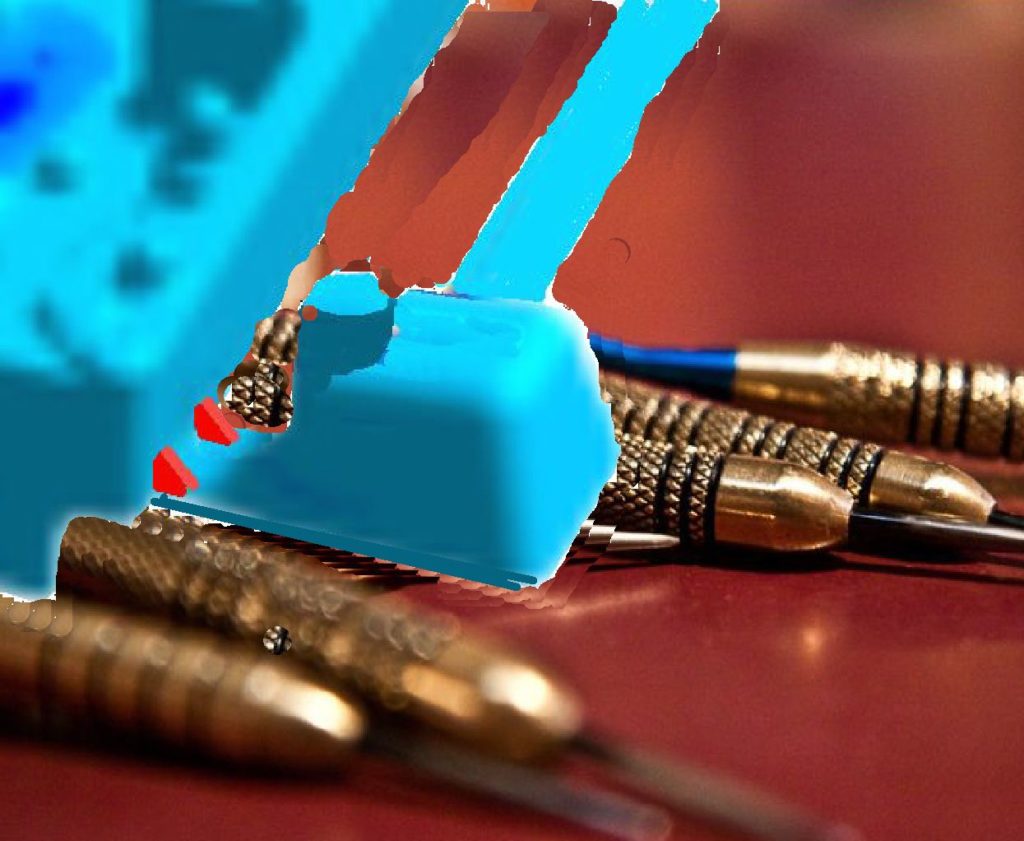
Die Casting would be a lot easier if there were a single trick to making a die run profitably. My experience is opposite to that. It takes a whole bunch of details done near optimum to make a smooth running job. A set of darts on a overflow transfer is just one example. At one shot per minute it is really easy to fill a pit or make a mess over the floor if a overflow wants to break off. Yes, thickening the transfer will keep it attached at the expense of trim break in and die spitting. A better solution is a pair of .7mm thick darts at either end of the transfer, This creates a structural channel cross section that cantilevers the overflow until it is time to trim. For those who don’t believe me, go back to sweeping overflows off the floor.

Hook

Ejector pin with ground in hook undercuts

Sometimes I wish that the tooling changes needed to implement a profit were more complicated. This would make it easier to explain why the casting plant is not making the profit it should. Hooks fit into that category. Every casting that falls into the pit subtracts from the profit. Adding hooks onto a couple overflow ejector pins neatly solves that problem. I am showing a tri hook variation that retains the casting even if the ejector pin spins. Yes it is possible to hand grind in hooks even if the die is in the machine.

Early casting machines used bumper rod ejection. Yes the part was ejected by the time that the die was open. Hooks on two overflow ejector pins kept the casting from falling into the pit. I would like the automation that I implement to achieve a better cycle time than the best a man can achieve. Profitable automation not only ejects the part by the time the die is open but also has the extract robot there at the same time to grab the casting.

Blow Back

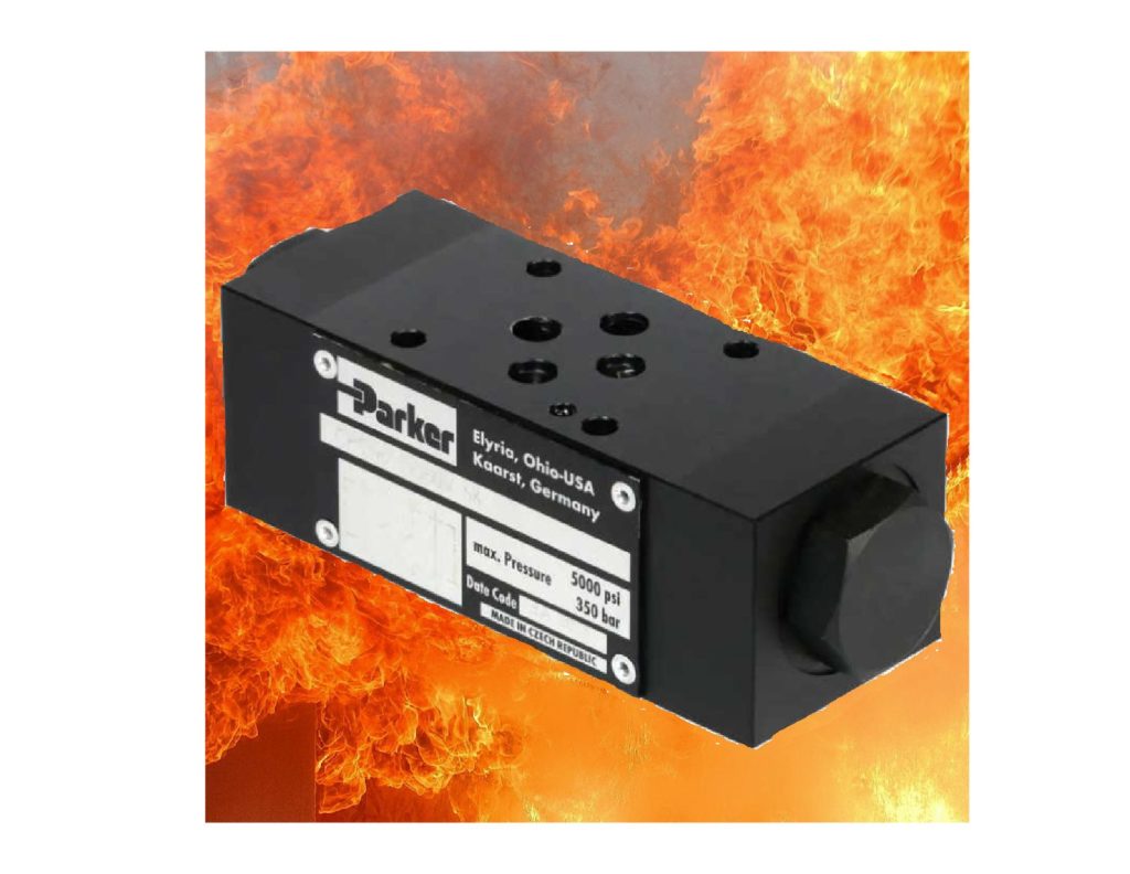
Hydraulic pilot check valves prevent cylinder motion when it is not wanted

Necessity is the mother of invention. Die castings have evolved from shapes that you can manufacture with an open shut die, into the current typical die casting that has slides and cores. This is to make a die casting more valuable than a stamping. Staying in business as a die caster involves upgrading the casting machines to support dies with more slides and subcores.

Subcores have difficult die design issues when they are larger than 25mm in diameter. The intensified metal pressure on the front of the subcore easily can exceed the locking force applied by the hydraulic cylinder. The core blows back when this is true. This problem is even worse when the casting machine can only deliver 1500 psi (103 bar) hydraulic pressure. Older casting machines may compound the difficulty by dropping hydraulic pressure due to shot motion. The traditional solution is to use a subcore lock run by an additional cylinder. This solution become problematic when the number separate cylinder motions exceeds the available core valves on the machine. Even more of a problem when a OEM PLC program lock prevents implementing the cylinder motion cycles needed to support a slide lock

Enter the creative solution. Pilot check valves prevent fluid from exiting from hydraulic cylinders when the direction valve is not energized. My first attempt was to stack a pilot check valve under the direction valve on the machine. Unfortunately the hoses balloon to much and unacceptable blow back occurs. The successful implementation of pilot check valves came by using a custom manifold on a O-ring port hydraulic cylinder. The rigid connection between the cylinder and D05 pilot check stopped blow back. As a bonus the full pilot check valve rated 350 bar holding pressure was available even though the machine only had 1500 psi-100 bar or less of hydraulic pressure (you also need cylinders that can handle (5000 psi- 350 bar pressure)

Knit Lines

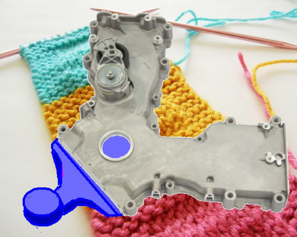
Ford Front Engine Cover with gating sketched in

A weakness in a casting caused by molten streams of metal incompletely joining back together. In actual castings knit lines result in leaks in pressure tight castings or tears in structural castings. A common cause of knit lines is multiple gate inlets. Part geometry and/ or a desire to use trimmable gates (thickness less than 3mm) cause high pressure die cast designers to use multiple inlets. For critical castings, knit lines result in downstream quality sorting such as 100% pressure testing or die penetrant testing.

When both casting and machining are contracted together other options are possible. The pictured front engine cover was made using a continuous single gate. To obtain enough gate area this gate was thicker than the 3mm maximum that enables a conventional trim without break in. A crop was used to remove the gate. This was a pair of 8 inch cylinders in both top and bottom halves of the trim.The cylinders push at each other after the trim die closes and trims the rest of the perimeter. The disadvantage is that a 3mm gate projection remains. Not a problem for the milling cutter in this case.

The hole for the crankshaft was also filled in. An extra cutter was incorporated into the boring tool to handle the trim projection in this area.

It is always more effective to engineer out defects. The lack of knit lines in this design eliminated the normal pressure test. I can assure you that even 100% pressure testing will not catch all the leakers.