Short shots and industrial case studies: Understanding fluid flow and solidification in high pressure die casting
Paul W.Cleary
JosephHa
MaheshPrakash
ThangNguyen
Flow modelling is one of the very useful tools in the high pressure die cast design tool box. It allows the die designer to explore various gating and venting option before cutting steel. This can save a major die redesign expense. It is an empirical tool. That is to say that it is only an approximation.
The first step in using the flow modelling tool is knowing where it is financially useful. I will discuss two important uses. Die venting is probably the most important. The vents / overflows do not expel gas from the cavity if they are blocked with metal. Flow modelling should be used to choose a fill order that results in the vents filling last. The second use is for gate arrival on multi-cavity dies. Most die castings must be intensified before the metal is frozen. This does not occur when some cavities fill early. The rise in pressure does not occur until all cavities are filled. The early filled cavities are already solidified which spoils the effectiveness of intensification.
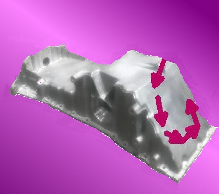
The second step is knowing when not to use the flow modelling tool. Once the die is complete and castings can be made, a short shot is a better way to discover the actual fill order. The pictured example of a research and development test mold shows a common deviation from reality. On many dies the metal likes to race ahead and block the vent path. You will only know that this is occurring by looking short shots. Also the current flow model programs are not good at predicting gate arrival on multi-cavity dies.

