
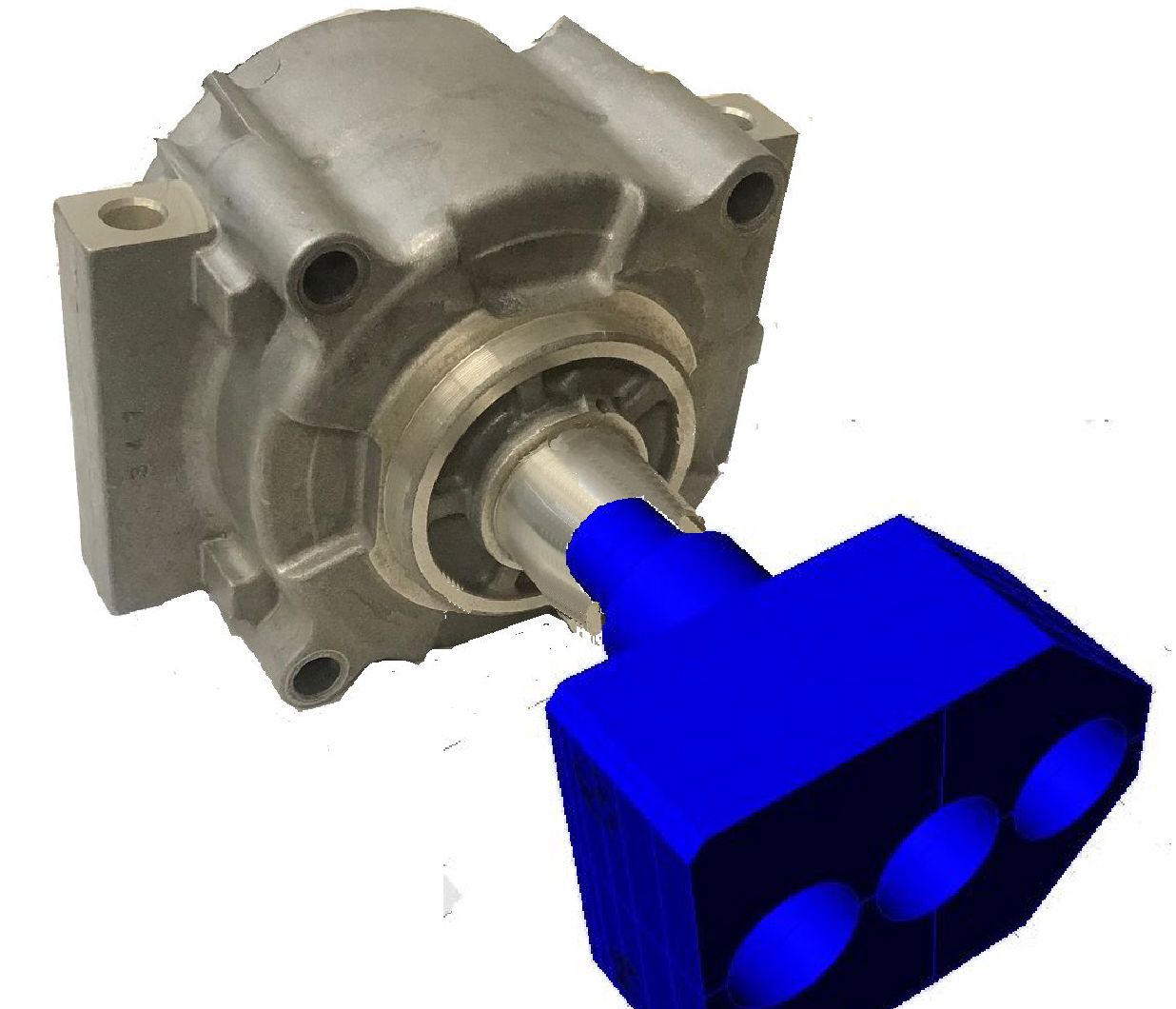
There are times in the economic cycle where it would be nice to have additional casting business to fill empty machine capacity. This usually means taking over an unprofitable job at the same selling price. In many cases it will require creative die design to make the difference. I have pictured an example. A four cavity 900 ton die without slides made the pictured freon tight casting. Annual volume was a couple million which would fill a couple machines. This part was being run at a competent competitive plant at a loss due to poor yield. The OEM could not accept a price increase or changes to the part design. The competitors dies being run were designed from standard die detail hardware and cores.
The competitors dies used a core pin to form the inside of the nose of the casting. This pin overheated because it was short and buried deep in the cover insert such that it is difficult to spray. Water cooling this standard H13 core as suggested by my boss was not the answer. H13 does not accept a high thermal gradient. H13 cores or inserts with water closer than 19mm to molten metal usually split. A water cooled H13 core split on the 4th shot after it was implemented.
Enter exotic material. Maraging steel (Marlock was the first widely used example) tolerates a higher thermal gradient than H13. Inserts and cores can be implemented with water as close as 6mm to molten aluminum. Incorporating the percolator head and retaining bar into the core created enough heat transfer surface within the core. {Conformal 3D printed cores also use maraging steel for the same reasons}
Massively cooled finger segments only solve part of the problem. With massively cooled
finger segments it is easy to over cool. This sometimes can be solved by using hot oil within the core. Because hot oil only has 1/2 the heat transfer capability of water it would not work on this finger segment. Because we purchased our Buhler casting machines with cooling water timers, this was the most effective solution. The cooling water flow could be shut off before the finger segments become too cold. (the four finger segments (1 per cavity) were piped into a separate zone) You will also notice that the chosen finger segment detail has a lot of extra size which serves as a storage reservoir for heat.
I am the first one to avoid inventing custom details. The wheel is round and does not need to be reinvented. Finger segments emerge as one area where creative design can change the casting yield. Taking over jobs that are unprofitable at a competitor plant only help your bottom line if you can make them profitable. Custom finger segments improve both yield and cycle time changing profitability.
