It is hard to imagine a life before we used electric lights
The introduction of bright plant lights made 3 shift operations possible. Sufficiently bright lighting is interpreted by the workers internal clocks as sunlight. In most 24 hour settings it is important that the off shift workers are alert and attentive. This is only possible if their internal systems think that it is time to be awake. You would not want everyone to be asleep if you arrive at the hospital emergency room at 3:00 am.
Times when we are without lights turn into events in our lives. I can still remember one evening when we were having a boxed murder mystery party with friends. In the middle of the game our house lights went out. This looked suspicious because of a lack of bad weather and the neighbors houses with lights on that were visible through our windows. ” OK, How did you do it?” My friends know that I am an engineer.

Even though I was the murderer in our game, the loss of lights was the local utility company transformer giving up the ghost.
Lights out manufacturing is one of those “overnight” revolutions that have been in the works for more than 20 years. In the 90’s there were very few pieces of manufacturing equipment that you could trust to run overnight unattended. Electrical Discharge Machining (EDM) was one of the first manufacturing processes to be used in a lights out fashion. Yes, we did need to add automatic halon fire extinguishers just in case.
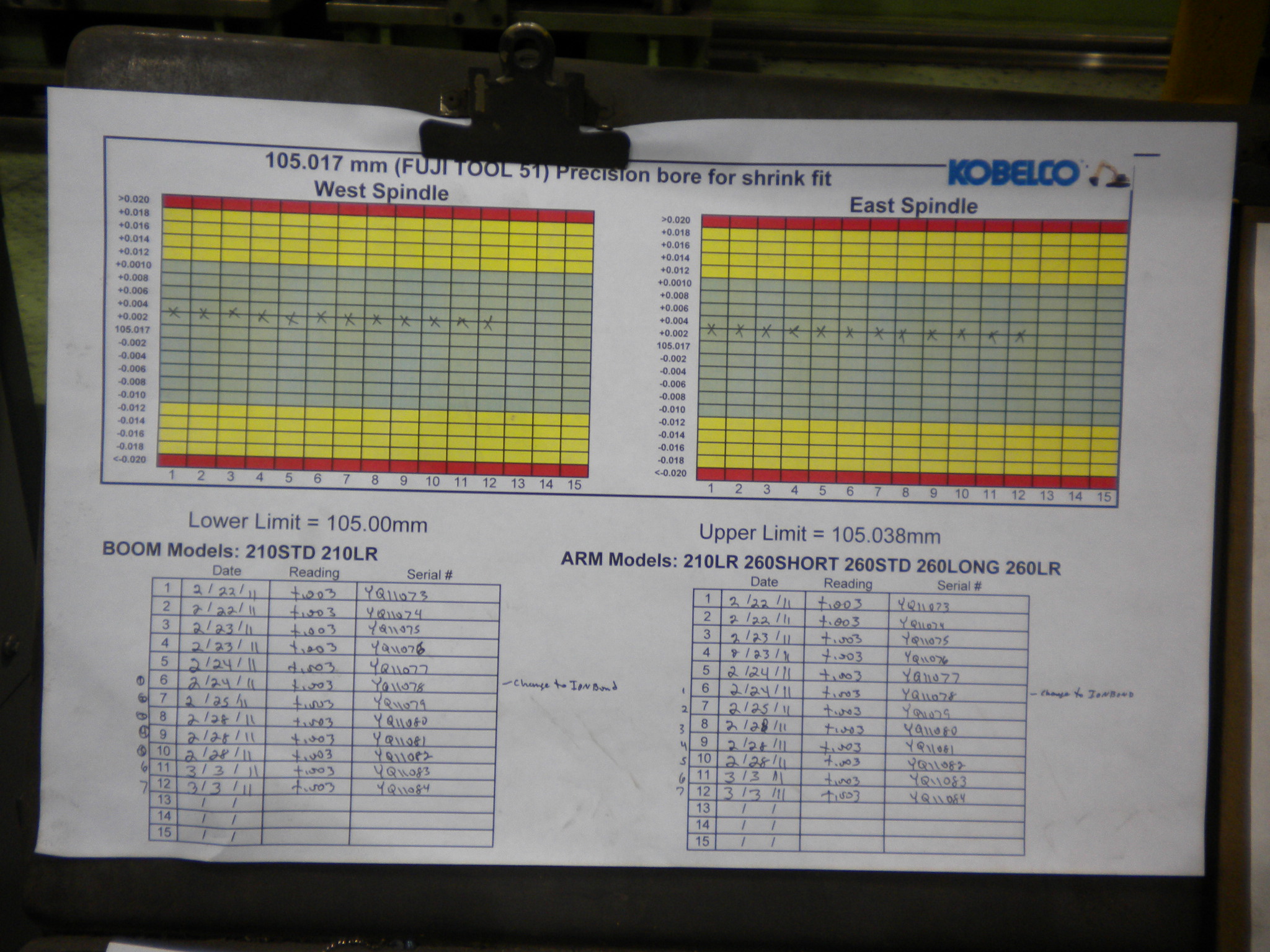
The highest precision manufacturing processes like EDM occur at slow speeds
This process is heavily used in mold making. It was a natural for unattended operation because some of the cuts can take days to accomplish. Many mold shops run their expensive EDM machines unattended overnight and over the weekend.
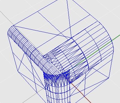
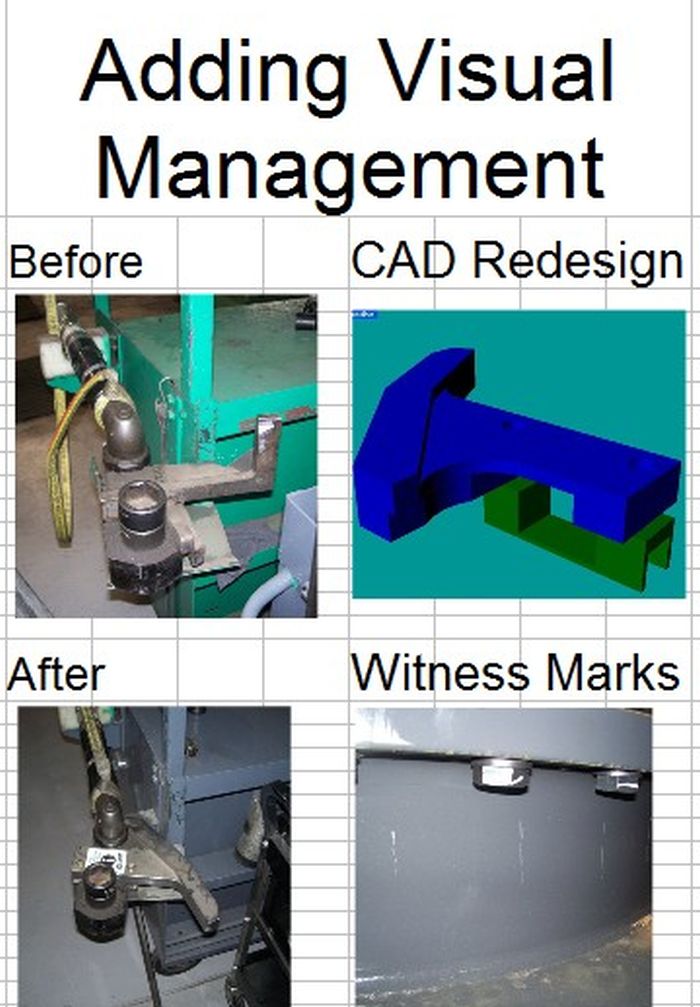
Lights out manufacturing has emerged from the bowels of tool and die manufacturing. A couple factors are responsible because implementing lights out manufacturing is not as simple as running over to the electrical breaker panel and snapping off the lights. ( Usually chaos ensues when the lights fail while people are working.) First our control systems are more reliable. Second, we can include more sensors to handle adjustment or shutdown if we are not present. Third we have adopted more slow speed manufacturing processes like 3D printing which take long periods to accomplish.
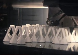
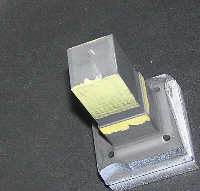
Photo courtesy of i.materialize.com
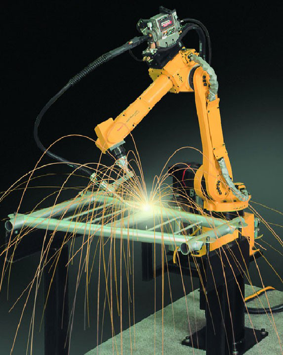
A good modern example of lights out manufacturing is the Amazon (Kiva) robots that happily operate in a dark warehouse because they are part of a system that was initially set up to operate in that fashion. Welding robots are another good example because they have the sophisitcated controls the enable then to run unattended. Welding robots can finish the job they are on after everyone goes home because of proper engineering design.
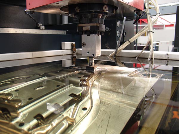
Laser and water jet cutting machines for sheet material can operate in a lights out manufacturing environment. The usually means that the jobs are packaged into full sheet set-ups so that sufficient time is gained by finishing jobs after everyone goes home.
We all remember the fairy tales of our youth where the elves came and did our work while we slept. It is more than a fairy tale. I still find it amazing seeing the progress that occurred while I slept when I arrive at work in the morning. Manufacturing will come back to North America. Some of it will come back as lights off manufacturing. Innovators in the manufacturing space have discovered that it is necessary to implement the latest manufacturing techniques and equipment to make a profit at an attractive selling price.