Hook

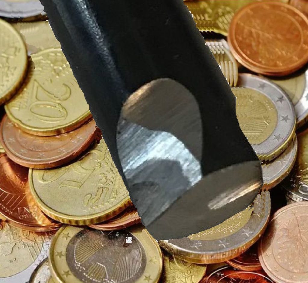
Ejector pin with ground in hook undercuts

Sometimes I wish that the tooling changes needed to implement a profit were more complicated. This would make it easier to explain why the casting plant is not making the profit it should. Hooks fit into that category. Every casting that falls into the pit subtracts from the profit. Adding hooks onto a couple overflow ejector pins neatly solves that problem. I am showing a tri hook variation that retains the casting even if the ejector pin spins. Yes it is possible to hand grind in hooks even if the die is in the machine.

Early casting machines used bumper rod ejection. Yes the part was ejected by the time that the die was open. Hooks on two overflow ejector pins kept the casting from falling into the pit. I would like the automation that I implement to achieve a better cycle time than the best a man can achieve. Profitable automation not only ejects the part by the time the die is open but also has the extract robot there at the same time to grab the casting.

Blow Back

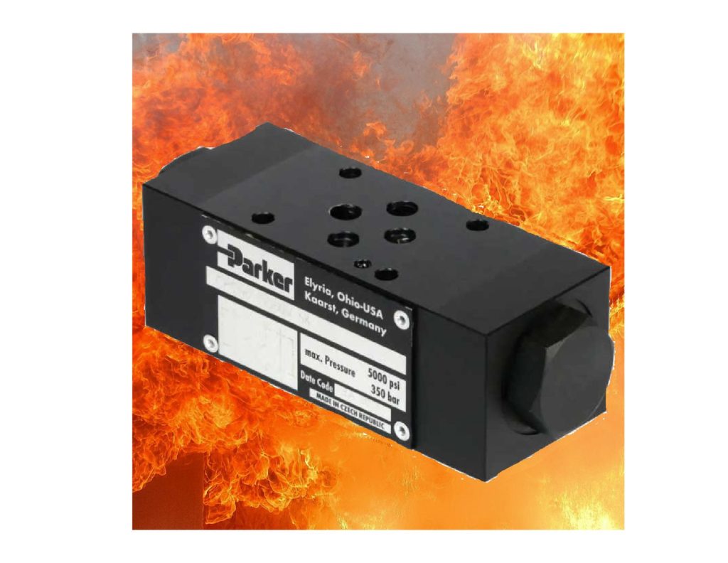
Hydraulic pilot check valves prevent cylinder motion when it is not wanted

Necessity is the mother of invention. Die castings have evolved from shapes that you can manufacture with an open shut die, into the current typical die casting that has slides and cores. This is to make a die casting more valuable than a stamping. Staying in business as a die caster involves upgrading the casting machines to support dies with more slides and subcores.

Subcores have difficult die design issues when they are larger than 25mm in diameter. The intensified metal pressure on the front of the subcore easily can exceed the locking force applied by the hydraulic cylinder. The core blows back when this is true. This problem is even worse when the casting machine can only deliver 1500 psi (103 bar) hydraulic pressure. Older casting machines may compound the difficulty by dropping hydraulic pressure due to shot motion. The traditional solution is to use a subcore lock run by an additional cylinder. This solution become problematic when the number separate cylinder motions exceeds the available core valves on the machine. Even more of a problem when a OEM PLC program lock prevents implementing the cylinder motion cycles needed to support a slide lock

Enter the creative solution. Pilot check valves prevent fluid from exiting from hydraulic cylinders when the direction valve is not energized. My first attempt was to stack a pilot check valve under the direction valve on the machine. Unfortunately the hoses balloon to much and unacceptable blow back occurs. The successful implementation of pilot check valves came by using a custom manifold on a O-ring port hydraulic cylinder. The rigid connection between the cylinder and D05 pilot check stopped blow back. As a bonus the full pilot check valve rated 350 bar holding pressure was available even though the machine only had 1500 psi-100 bar or less of hydraulic pressure (you also need cylinders that can handle (5000 psi- 350 bar pressure)

Knit Lines

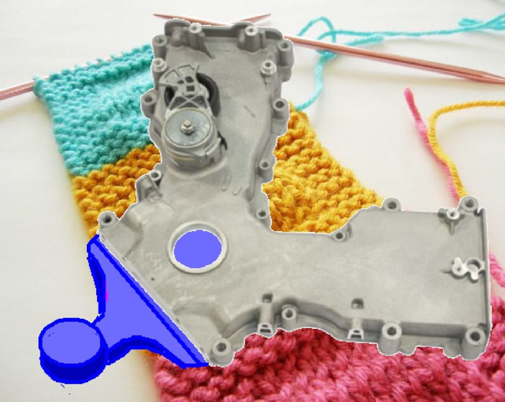
Ford Front Engine Cover with gating sketched in

A weakness in a casting caused by molten streams of metal incompletely joining back together. In actual castings knit lines result in leaks in pressure tight castings or tears in structural castings. A common cause of knit lines is multiple gate inlets. Part geometry and/ or a desire to use trimmable gates (thickness less than 3mm) cause high pressure die cast designers to use multiple inlets. For critical castings, knit lines result in downstream quality sorting such as 100% pressure testing or die penetrant testing.

When both casting and machining are contracted together other options are possible. The pictured front engine cover was made using a continuous single gate. To obtain enough gate area this gate was thicker than the 3mm maximum that enables a conventional trim without break in. A crop was used to remove the gate. This was a pair of 8 inch cylinders in both top and bottom halves of the trim.The cylinders push at each other after the trim die closes and trims the rest of the perimeter. The disadvantage is that a 3mm gate projection remains. Not a problem for the milling cutter in this case.

The hole for the crankshaft was also filled in. An extra cutter was incorporated into the boring tool to handle the trim projection in this area.

It is always more effective to engineer out defects. The lack of knit lines in this design eliminated the normal pressure test. I can assure you that even 100% pressure testing will not catch all the leakers.

Short Shot

Comparison of predicted and actual flow within a high pressure die casting


Short shots and industrial case studies: Understanding fluid flow and solidification in high pressure die casting
Paul W.Cleary
JosephHa
MaheshPrakash
ThangNguyen


Flow modelling is one of the very useful tools in the high pressure die cast design tool box. It allows the die designer to explore various gating and venting option before cutting steel. This can save a major die redesign expense. It is an empirical tool. That is to say that it is only an approximation.
The first step in using the flow modelling tool is knowing where it is financially useful. I will discuss two important uses. Die venting is probably the most important. The vents / overflows do not expel gas from the cavity if they are blocked with metal. Flow modelling should be used to choose a fill order that results in the vents filling last. The second use is for gate arrival on multi-cavity dies. Most die castings must be intensified before the metal is frozen. This does not occur when some cavities fill early. The rise in pressure does not occur until all cavities are filled. The early filled cavities are already solidified which spoils the effectiveness of intensification.
The second step is knowing when not to use the flow modelling tool. Once the die is complete and castings can be made, a short shot is a better way to discover the actual fill order. The pictured example of a research and development test mold shows a common deviation from reality. On many dies the metal likes to race ahead and block the vent path. You will only know that this is occurring by looking short shots. Also the current flow model programs are not good at predicting gate arrival on multi-cavity dies.