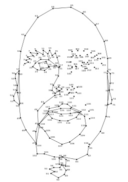
We all learned to create
pictures by connecting the dots.
A simple child’s task like connecting the dots matches a computer’s capability. This was especially true in the early days when computer numeric controls had a lot less intelligence. It was a stretch for the computer to perform a simple 2 dimensional connect the dot task. Even todays CNC (Computer Numerical Control) is based on connecting dots with straight lines.
We began the computer controlled manufacturing revolution by using simple 2 dimensional dot to dot. In the very beginning there were long distances between the dots. The parts that were CNC manufactured had facets like you see on diamonds. As Moore’s law has given us more computer memory and horsepower we use ever greater numbers of dots to the point where the facets caused by straight line connecting of the dots are perceived as a smooth blend. A simple 2 dimensional approximation of a circle using a ring of dots connected by straight lines has evolved into a the chain of connected dots that has lengthened to stretch many miles.
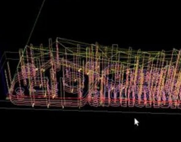
A string of connected dots, many miles in length guides the path of a cutter used to make a mold
As we acquired more computer horsepower we wanted to expand into three dimensional objects. We again looked for the simplest way. A straight line connecting two dots was evolved into a set of three dots connected by straight lines defining a plane in three dimensions. Computer defined three dimensional objects look a lot like geodesic domes
 Tyranny of numbers came to get us. Whereas we were able to manually program CNC machining G-code and moon landings by creating the travel path dot by dot, it simply was not humanly possible to define all of the little triangles needed to define an object shape. The STL (STereoLithography) data format we created for the task actually is capable of defining just about any shape that we can conceive. It was the early 90’s before any version of CAM (Computer Aided Manufacturing) software could generate a complete enough STL shape definition to be commercially useful. It was the turn of the century before any CAD (Computer Aided Drafting) software caught up to the same level. The underlying issue is that most of the part shapes that we use are not pure cubes,cylinders or spheres. In the classic example, three different radii meet at a corner. What is the shape at the corner? Turns out the computer does not know either.
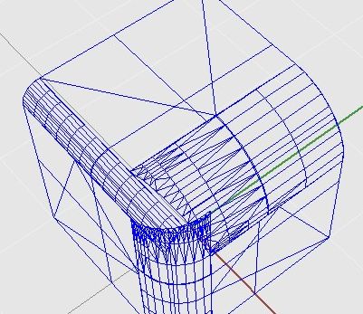
The historic solution to the three different radii meeting at corner, was to instruct the pattern maker to do a blend. The digital solution started out in a very similar fashion. The STL file was manually adjusted by a person. This time consuming and costly step is one of the impediments slowing the adoption of 3D printing. The incredibly slow 3D printing speed is fast compared to the time need to clean a STL data file triangle by triangle. Moore’s Law keeps advancing. Each generation of software and 3D printing hardware opens the door for new affordable uses. Even though 3D printing theoretically has the ability to create any shape, in the near term it will have economically imposed shape limitations like any other manufacturing process