Spaghetti

Gigacasting die hoses look like spaghetti

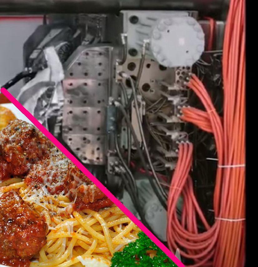
I always find a good dish of spaghetti attractive. My wife buys our favourite tomatopasta sauce and adds in the meatballs. In all the years of eating spaghetti I have never counted the number of strands on my dish. Usually they are eaten before that is possible. I cannot imagine having to number each of the strands of spaghetti that are on my dinner plate. Numbering the hoses feeding a gigacasting die is just the beginning of utilizing them to achieve the correct temperature distribution in a die

Now we have gigacasting dies. As you can see in the picture more than 100 hoses are connected to each half of the die. The “spaghetti” gets worse when you realize that each hose feeding the die is looped into 3 to 7 thermal passages within the die. I am not surprised. Elon said that a gigacasting combined 70 pieces into one. The thermal passages you would use to make 70 individual casting dies got incorporated into a single die. Even the huge slides used to create the rear wheel housings have a large numbers of percolator style thermal passages in the fingers that form the rear rail section.

Die casting dies that are at room temperature do not produce good castings. Die preheating is used to avoid scrapping up to 100 castings to bring the die up to steady state operating temperature. Gigacasting dies weigh 100,000 Kg. Using the 490 J/Kg C heat capacity of steel, 160 Kw Hr of power input is needed to increase the die insert temperature to 100C and raise the holder temperature to 75C assuming no losses. Actual heat input requirements are double that factoring in convection losses and platen heating.

A pair of 90 KW hot oil Thermal Control Units (TCU) happily preheat a gigacasting die for prototyping if left on overnight. When a long preheat period is available other issues like having enough heat transfer passage length are not a concern. Gigacasting integrated into an assembly plant is another issue. 2 hours of assembly plant shutdown waiting for a die to preheat is an eternity, I suspect that the hose “spaghetti” we see is to enable the use of 5 additional 48KW TCU’s to reduce the preheat time to under an hour.

Biscuit

Gigacastings also need biscuit thickness control

It is easy to think about biscuits at this time of year. My wife and I bake a whole bunch of them to pass around at this time of year. As this Gigacasting image shows the casting operator was also thinking about other types of biscuits.
Control of biscuit thickness is normally a significant process control variable. Even if the molten metal delivery device is able to accomplish perfect weight dosing, other causes of biscuit length variation must be controlled. Die blow and flashing also vary casting weight which show as a biscuit thickness variation Usually a minimum biscuit thickness is needed to insure that molten metal is available to fill in porosity as the metal shrinks during solidification. This is most important when you are producing aluminum castings that are pressure tight. Fortunately structural gigacasting castings usually do not have a leak tight requirement. This probably explains why this gigacasting has a non traditional biscuit shape. It probably also explains why it is possible to place less emphasis on biscuit thickness control

Rigid

Gigacasting dies must be very rigid

Top flight gymnasts put a lot of effort in being flexible. Gigacasting die designers do the opposite. They try very hard to make their dies rigid. In the case of the pictured rear underbody gigacasting die that is accomplished by combining most of the traditional ejector box into the die holder itself.

One of the early lessons taught to mechanical engineers is that materials deflect under applied loads. I can assure you that there is no shortage of applied loads in high pressure die casting. I thought that a 1000 ton press was massive as a new die cast engineer. Now we see 10,000 ton high pressure die casting presses. When you see the blocks of steel used to make high pressure die cast platens, it is hard to picture them flexing

This discussion is about the flexing of the ejector platen. On a 400ton die casting machine you can pretty much ignore ejector platen flexing. The ejector die itself is rigid enough to bridge across the platen face. On a 4000 ton die cast machine and larger platen flex is an important consideration. The style of clamping mechanism is also a factor. There are four common styles.

Vertical pin axis book links

Horizontal pin axis book links

4 corner links

Hydraulic cylinder 2 platen

It is usually necessary to design the ejector die to match the style of machine clamp. Dies run in machines that they were not designed for are well known for flashing.

Large dies with slides will flash. Even if you are able to blue the die to shut off at room temperature, the first shot is not at steady state. Die require 30 to 100 shots to reach steady state even with preheat. Properly designed dies eject all flash every shot. This avoids die damage related to closing on flash. Remember the machine could be applying 10,000 tons on a small piece of flash

Cross Hatch

Gigacasting and Pistons both utilize cross hatch to control miss runs

It is interesting that the laws of physics do not change just because you are trying to make high quality gigacastings. Structural gigacastings must be free of miss runs just the same as structural pistons. I am not surprised that the cross hatch invented to solve miss run piston defects is now appearing as a feature of gigacastings.

My casting mentors conjectured that the cross hatch anchored the flow fronts and created a path for venting at the bottom of the grooves. All I can add to that is that the method actually solved piston miss run issues. Otherwise there is no structural need to have cross hatch on pistons. Gigacastings fit into the same category. There is no structural need for cross hatch but miss runs which cause cracks and weak spots are definitely a problem

Erosion

Die erosion is similar to river erosion

We have all witnessed the destructive power of fast flowing flood waters. Molten aluminum has nearly the same viscosity as water. A high pressure casting die witnesses a fast flowing flood every shot. It is not surprising that we see related erosion where the flow is the fastest. In die casting dies one universal fast flow location is downstream of the gate. In this pictured example of a die making structural castings the erosion downstream of the gates is clearly visible. Obviously this creates textured casting surfaces if not major sticking problems.

Usually the die designers defend their design when this occurs. Most HPDC die design are created using the industry standard formula for gate size. They are based on using historic alloys injected just above the melting temperature. This strategy works well for most historic aluminum HPDC castings. It is possible to avoid erosion injecting secondary aluminum into molds that have a fill path length of less than 22 inches (0.55 meters) using the text book gating sizes and standard 120 in/sec (3.0 meter/sec) fast shot speeds. This makes sense because the standard formula use this as a basis.

However we as an industry are being asked to do more. Structural castings have fill path lengths greater than 22 inches and are made of primary alloy with low iron content. It is not surprising that we see major erosion when 280 in/sec (7.0 meter/sec) shot speeds and 1350F (732C) process settings are being used to fill the far end of the structural castings.

How do you solve die erosion. The simple answer is to design a die with better gating. Usually this is not an affordable option after a die is built and production has started. Die surface coatings are helpful. Due to the high cost of effective coatings they are best applied to local sub inserts. I like locally making the part wall thickness down stream of the gates 50% thicker. This 50% increase is blended back to standard wall thickness over about 3 inches (90 mm) Even though this will be out of part print it is easier to obtain forgiveness than permission.